Isotope geochemistry is based on the accurate and precise determination of elemental and isotopic compositions of rocks and minerals. Although some of the earliest geochronological methods (notably the 14C method, see Section 4.1) were based on the detection of radioactivity by means of Geiger-Müller counters and liquid scintillation detectors, nearly all modern isotope geochemistry is done by mass spectrometry.
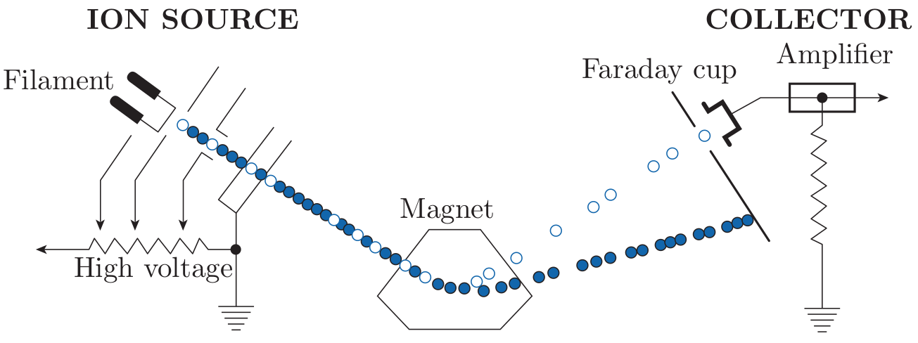
A mass spectrometer is a device that separates electrically charged atoms or molecules based on their mass, enabling precise measurement of the isotopic composition. A mass spectrometer consists of the following parts:
In the remainder of this section, we will assume the source to be a
filament and the mass analyser to be an electromagnet.
After pumping the mass spectrometer down to (ultra-)high vacuum
conditions (10-6 to 10-9 mbar), the sample enters the ion source as a gas,
where it is bombarded with electrons. The resulting ions (with charge e) are
accelerated in an electric field (with potential difference V ) and
collimated to a narrow beam. This beam is sent through a magnetic field
(with strength H) which deflects it into a circular trajectory with a
radius proportional to the ion mass (m). This results in a physical
separation of the incoming ion beam into various outgoing beams.
The beams of interest are steered into the ion detector which, in its
simplest design (the so-called ‘Faraday Cup’) consists of a long and
narrow cup. The ion beam is neutralised in the cup by electrons
flowing from ground through a resistor. The potential difference across
this resistor is measured and registered on a computer for further
processing.
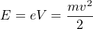
The electric field transfers a certain amount of kinetic energy to the ions:
|
| (3.1) |
With e is the electrical charge (in multiples of 1.60219 ×10⁻¹⁹C, which is the elementary charge of an electron. Because each type of ion has a different mass (m, in multiples of 1.660538 ×10⁻²⁷kg, the atomic mass unit), their terminal velocity (v) differs as well:
 | (3.2) |
The mass analyser deflects the ions according to the following equation:
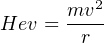 | (3.3) |
Substituting Equation 3.2 into 3.3 yields:
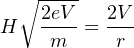 | (3.4) |
from which it follows that:
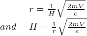 | (3.5) |
Equation 3.5 allows us to calculate the radius of the ion trajectory for any given mass-to-charge ratio m∕e. Note that light isotopes are more strongly deflected than equally charged heavy ones. Equation 3.5 can also be used to calculate the magnetic field strength required to deflect an ion beam with a given m∕e ratio into the collector. This is more practical because most mass spectrometers have a fixed radius so that the different ions must be collected by varying H. Some modern mass spectrometers are equipped with multiple ion collectors the enabling simultaneous analysis of several ionic masses.
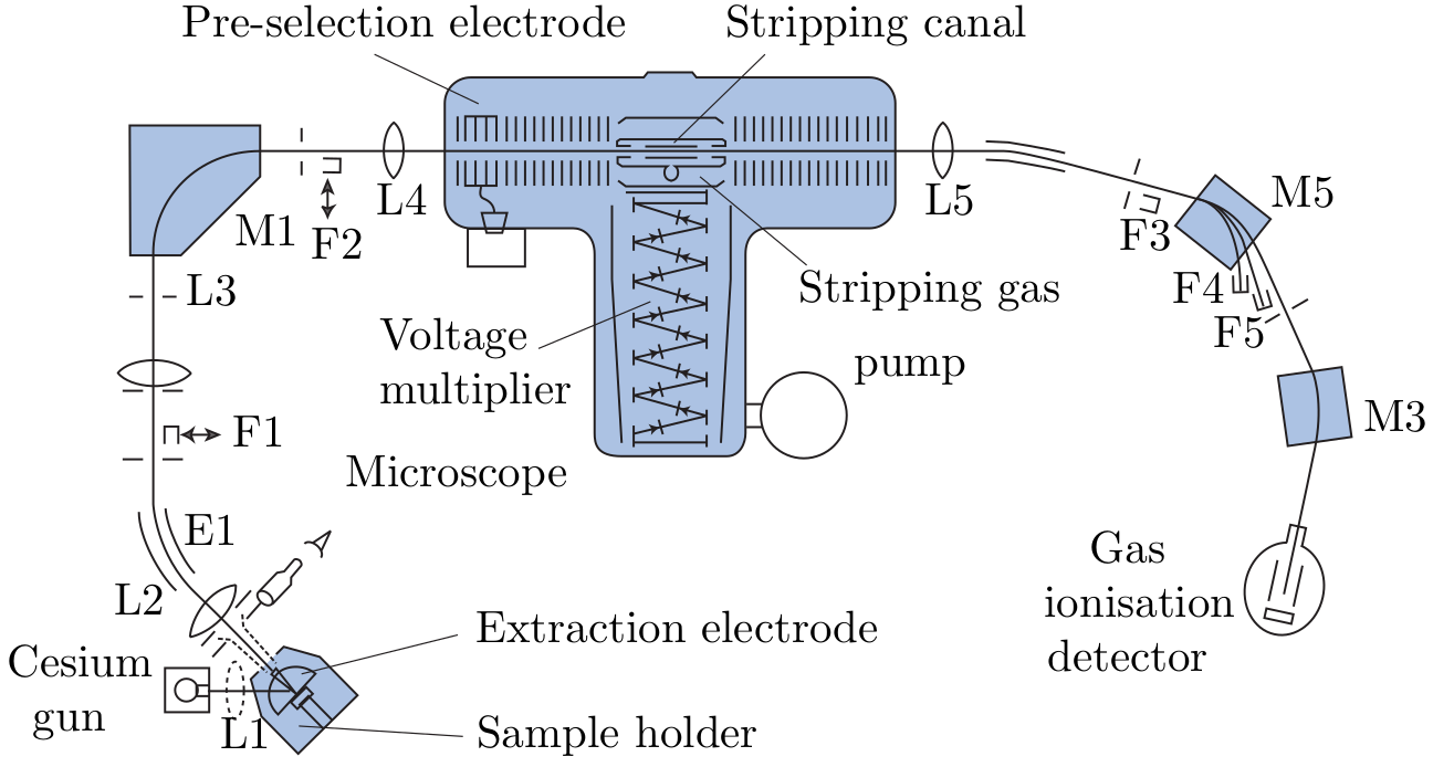
Several types of mass spectrometers are used for geoscience applications:
 ). The resulting
beam is accelerated in the first part of the tandem accelerator
by a potential difference of several million eV, and sent through
a thin chamber filled with a ‘stripper’ gas. Collisions of stripper
gas atoms with the incoming ions destroys any molecular bonds
and forms 3+ ions in the process. The beam now consists of
purely atomic ions, which are accelerated in the second part of the
accelerator and steered into a second mass analyser. The AMS
has revolutionised the 14C method by enabling the analysis of
extremely small (mg-sized) samples (see Section 4.1), and has
enabled a whole new field of geochronology based on the analysis
of terrestrial cosmogenic radionuclides (Chapter 8). The main
limitation of AMS is its high cost. Currently only two AMS
facilities are operating in the UK (in Oxford and Glasgow).
). The resulting
beam is accelerated in the first part of the tandem accelerator
by a potential difference of several million eV, and sent through
a thin chamber filled with a ‘stripper’ gas. Collisions of stripper
gas atoms with the incoming ions destroys any molecular bonds
and forms 3+ ions in the process. The beam now consists of
purely atomic ions, which are accelerated in the second part of the
accelerator and steered into a second mass analyser. The AMS
has revolutionised the 14C method by enabling the analysis of
extremely small (mg-sized) samples (see Section 4.1), and has
enabled a whole new field of geochronology based on the analysis
of terrestrial cosmogenic radionuclides (Chapter 8). The main
limitation of AMS is its high cost. Currently only two AMS
facilities are operating in the UK (in Oxford and Glasgow).
Besides determining isotopic compositions, the mass spectrometer can also be used to measure elemental concentrations, using a method called isotope dilution. This is done by mixing the sample solution (whose isotopic composition has already been determined) with a known quantity of a solution with a different (but known) isotopic composition and known elemental concentration. The latter solution is called the spike. The isotopic composition of the mixture is analysed by mass spectrometry. The measured isotopic ratio Rm for an element with two isotopes (aX and bX) is given by:
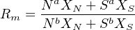 | (3.6) |
with
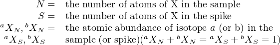 |
N is the only unknown in Equation 3.6, which can therefore be rewritten as:
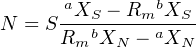 | (3.7) |
N can also be expressed as a function of the isotopic ratios in the sample RN(= aXN∕bXN) and in the spike RS(= aXS∕bXS). The atomic abundance of aX and bX in the sample are given by:
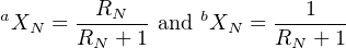 | (3.8) |
and in the spike:
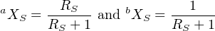 | (3.9) |
Substituting Equations 3.9 and 3.8 into 3.7 yields:
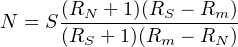 | (3.10) |
Equations 3.7 and 3.10 give the atomic concentration of X (in atoms/g). Dividing N by Avogadro’s number NA and multiplying with the atomic weights (g/mol) yields the corresponding weight percentages. Isotope dilution is a very powerful method because:
Isotope dilution is the ‘gold standard’ for isotope geochemistry, recommended when the most accurate and precise results are desired. Unfortunately, isotope dilution is also very time consuming and cannot be readily applied to micro-analytical techniques such as LA-ICP-MS and SIMS. In those cases, and alternative method is used, which is less precise (%- rather than o- level precision) but quicker. The idea is to normalise the signal ratios recorded by the mass spectrometer to a standard of known age. As before, let P be a radioactive parent which decays to a radiogenic daughter D. Suppose that we can measure both nuclides on the same mass spectrometer, yielding two electronic signal intensities SP and SD. These signals may be recorded in units of V, A, or Hz. We cannot directly use the signal ratios as a proxy for the isotopic ratio:

because the parent and daughter are two different elements with different chemical properties and ionisation efficiencies. We can, however, assume that the isotopic ratio is proportional to the signal ratio:
 | (3.11) |
Thus, if we double D (and thus D∕P), we would also expect to double SD (and thus SD∕SP). To determine the constant of proportionality C, we analyse a standard of known age (ts) and, hence (D∕P)-ratio (due to Equation 2.5):
 | (3.12) |
where λP is the decay constant of the parent and SPs∕SDs is the (inverse) signal ratio of the standard.