 Close
Close

The Design, Integration and Test section is by far the largest with a staff of around a dozen engineers. A wide range of areas of expertise exists. These exploit advanced techniques and devices to address the diverse requirements of differing space missions. Different space missions call for very different design approaches. For example some call for very high data rates whereas some require extreme miniaturisation and very low power consumption. All missions require high reliability techniques and to be engineered for the space vacuum and launch vibration environments. Most missions require radiation tolerant systems, the level of tolerance being dependent on the orbit and mission duration.
- Electronic Ground Support Equipment
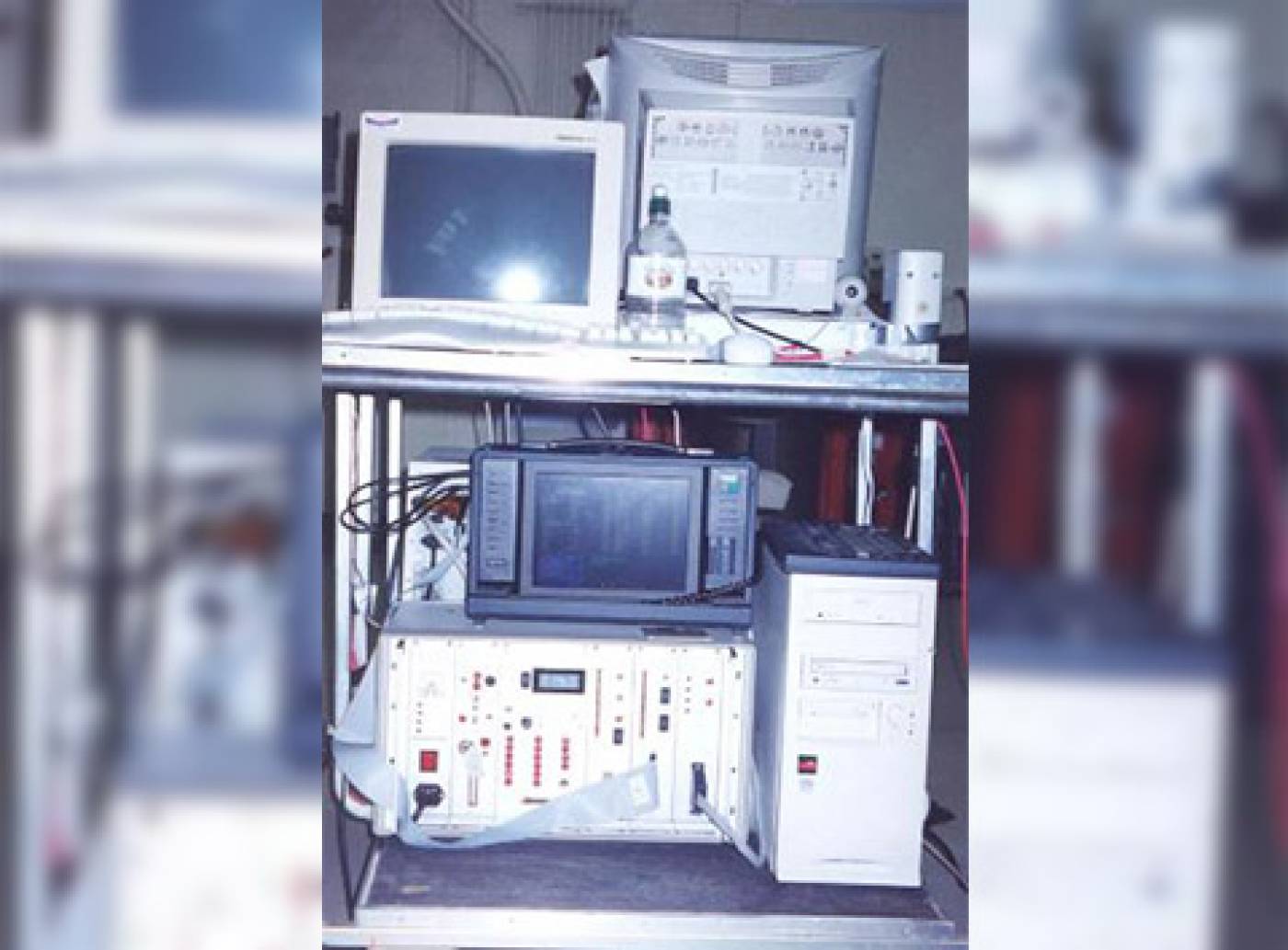
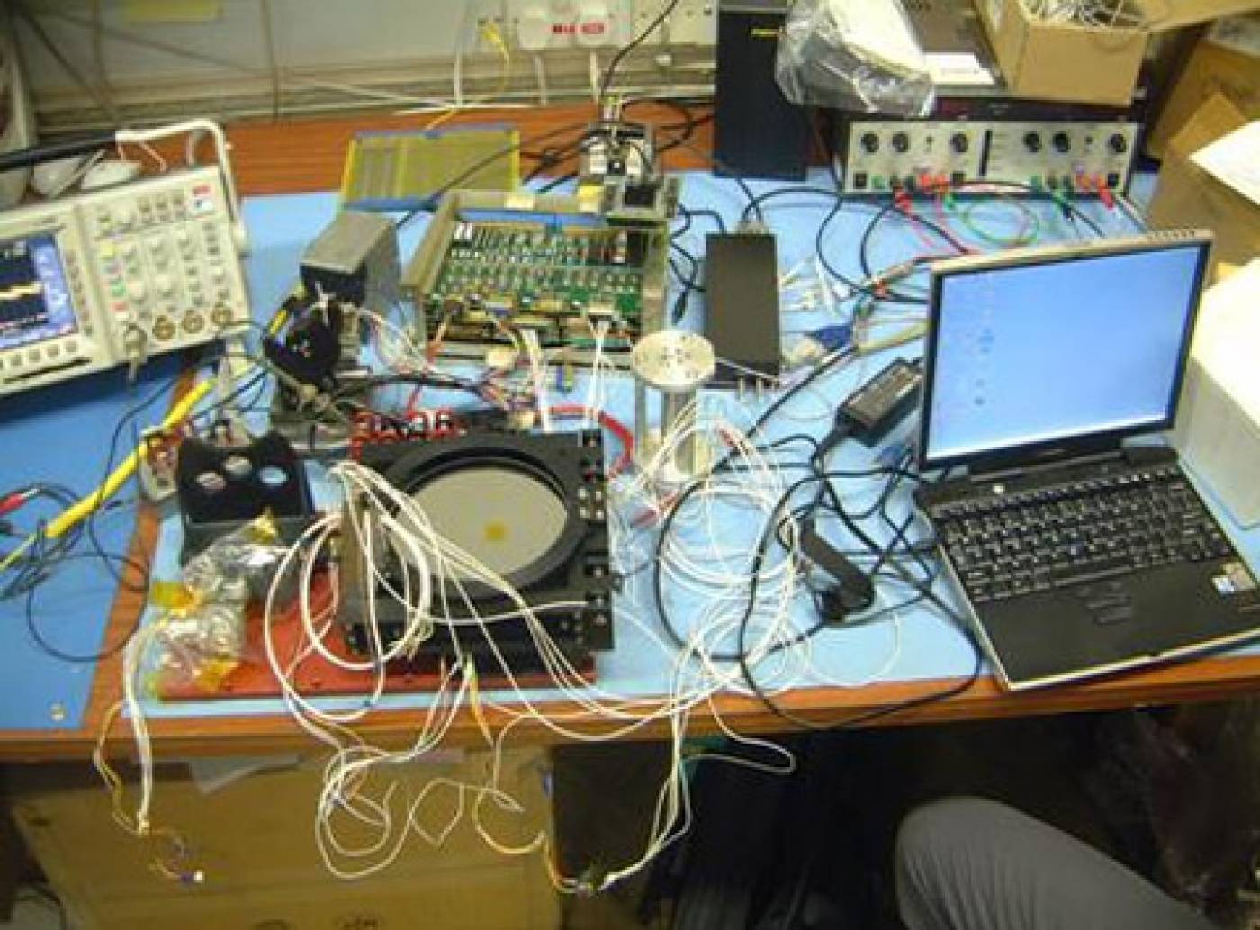
Testing equipment is essential to the production of the electronic boards and payload instruments at all levels of the system development. To this effect, we design passive and active Ground Support Equipment to test and calibrate our systems. The Electronic GSEs are often integrated with other test systems like vacuum chambers and optical GSEs and are PC controlled. Labview is now the most common software used for the EGSE control software.
- Electronic sub systems
We have expertise in designing:
- Low noise and/or high speed amplification.
- Analogue signal conditioning including: charge sensitive pre-amplifiers, general amplification, pulse shaping, bandwidth control, sample/peak detect & hold.
- Signal conversion including: analogue to digital varying from high precision to high speed, analogue processing such as ratiometric division.
- Clock waveform generation for the readout of CCDs and other image sensors.
- Digital processing both in discrete logic and microprocessor based systems.These systems can be very specific such as to decode the position of a photon arriving on a position sensitive detector or can be more general purpose such as the command and data handling system which commonly exercises overall instrument control and the interfaces to the spacecraft.
- High speed systems and high density FPGA systems are frequently implemented. Power conditioning, both low voltage (typically between 1W and 50W) and (low power) high voltage supplies, typically between 3 and 10kV. These all need to provide isolation and to adhere to very stringent EMC requirements.
- Electronic systems
Electronic systems are usually very complex with hundreds of interconnections between the various boards that compose the system. The challenging role of the electronic system engineer is to understand and capture the requirements of the system.
- Electronic testing
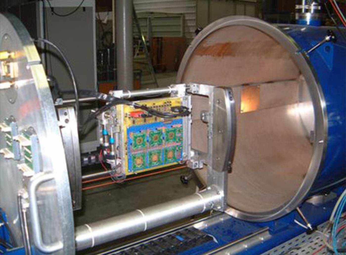
Due to the high level of validation required for the Flight equipement, extended tests are carried out:
- Space enviroment temperature extremes (+/- 80 C typically)
- Space radiation dose (TID, SEL, EU)
- Emited electromagnetic interference
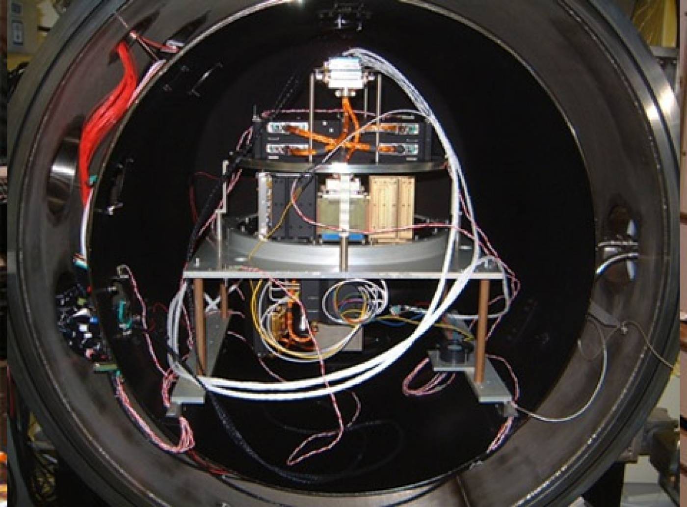
- Electronic systems integration
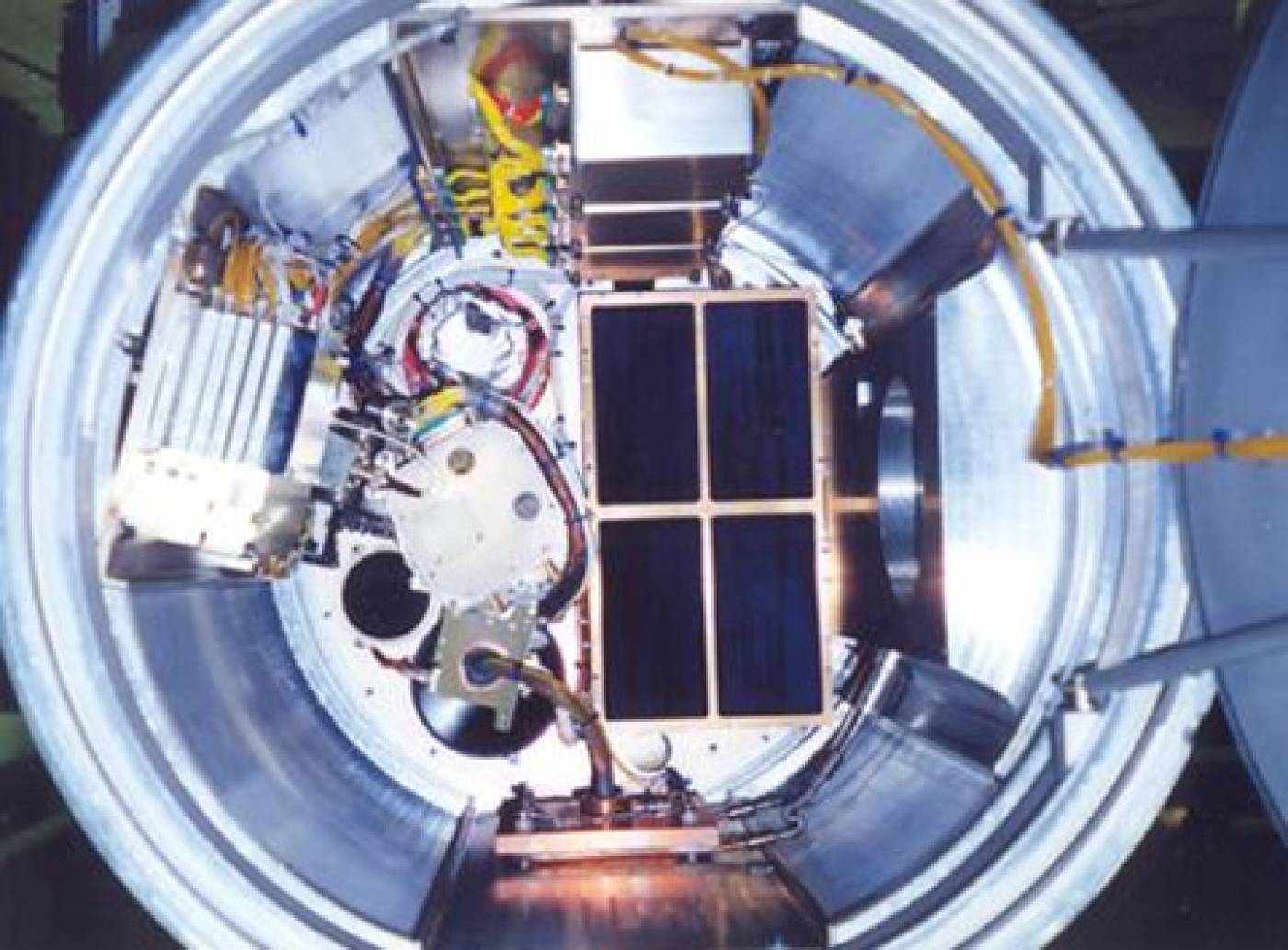
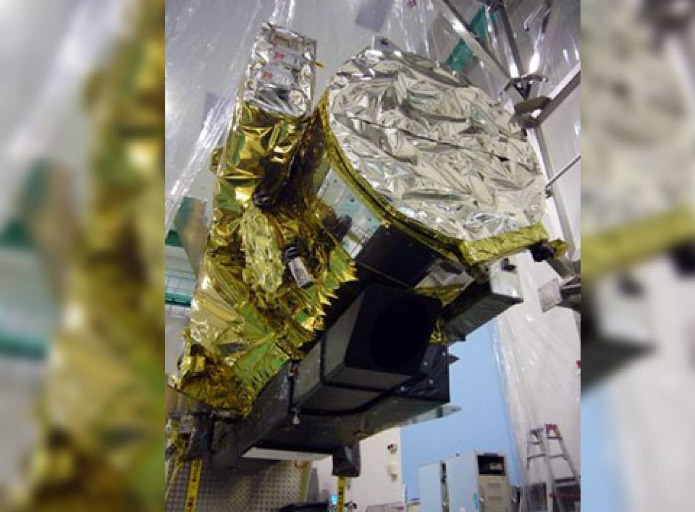
We actively take part and support the mission at all levels of integration. Once the system has been fully tested and comissioned at MSSL, the next stage is to accomodate our instrument in the next higher system assembly, usually this is the calibration system or the spacecraft, this requires the instruments to be taken to the relevant test facilities (Rutherford Appleton Laboratory in the UK, ESTEC in the Netherlands, Goddard Space Flight Center in the USA, etc..)
At sapcecraft level, once the two systems are connected, a new series of tests are conducted to verify that the instrument is working normally and that there are no issues wit the spacecraft mechanical, thermal, electronic and optical interfaces. Once the interfaces are verified, more tests are done for the final performance verification.

Cobalt 60 TID tests in ESTEC
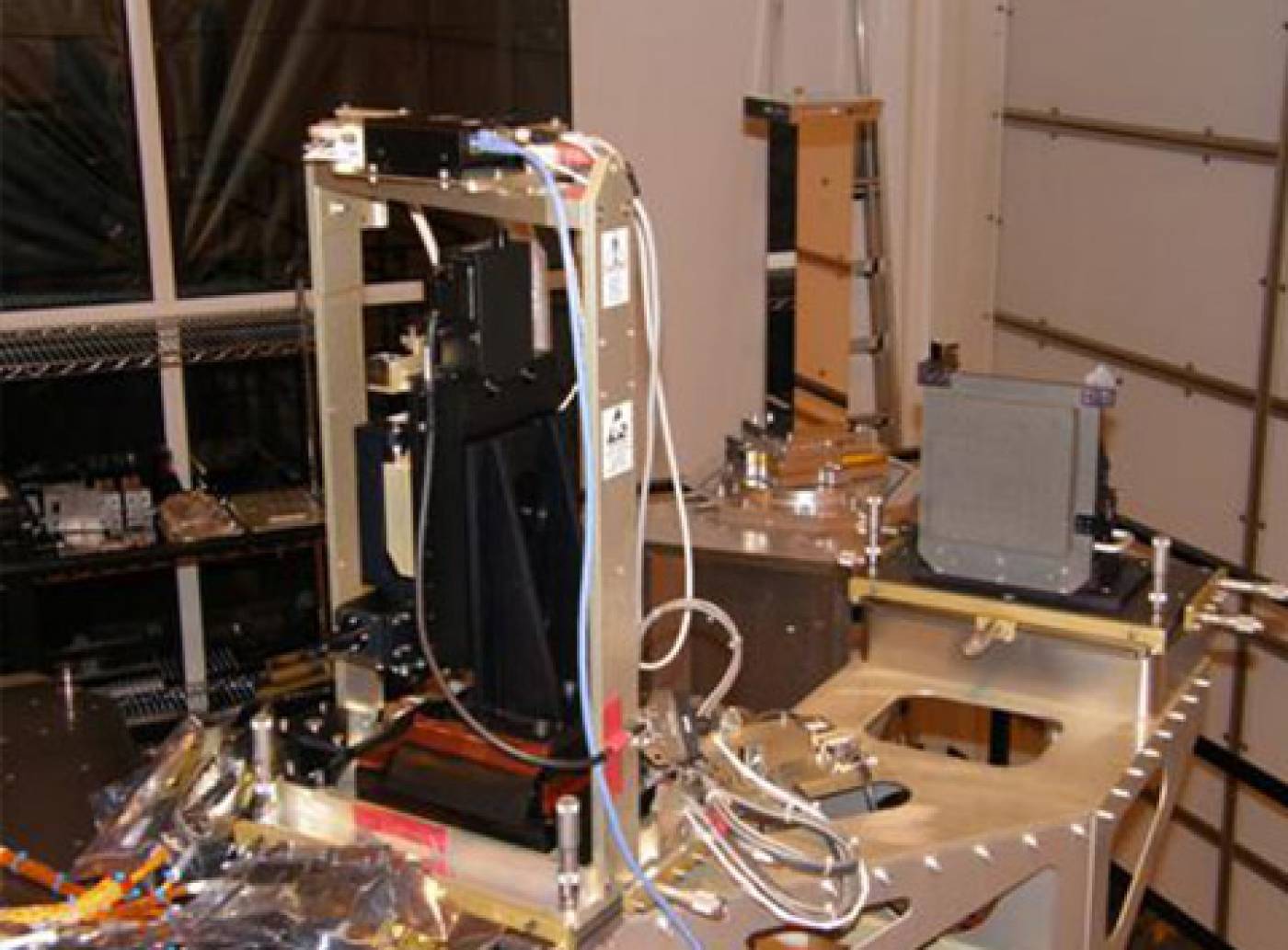
Flight thermal cycling and testing at MSSL
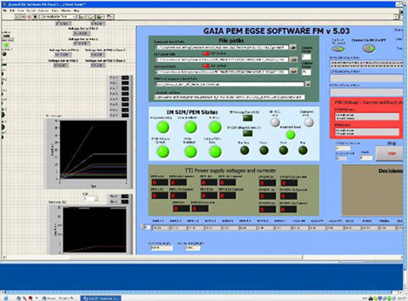
GAIA PEM-Coupling EGSE
Heavy ion latchup tests in Louvain La neuve
J-PEX EGSE
J-PEX sounding rocket integration
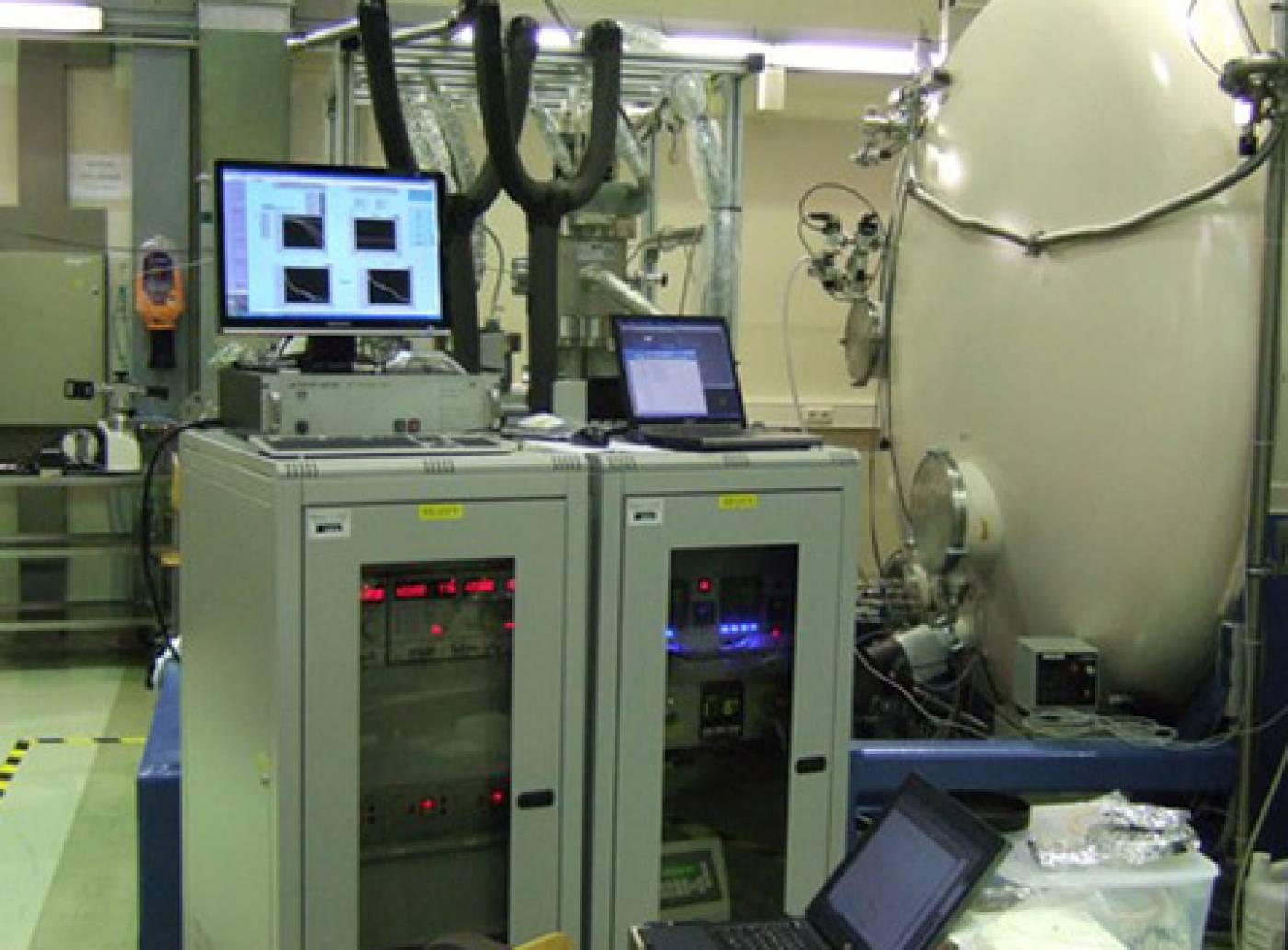
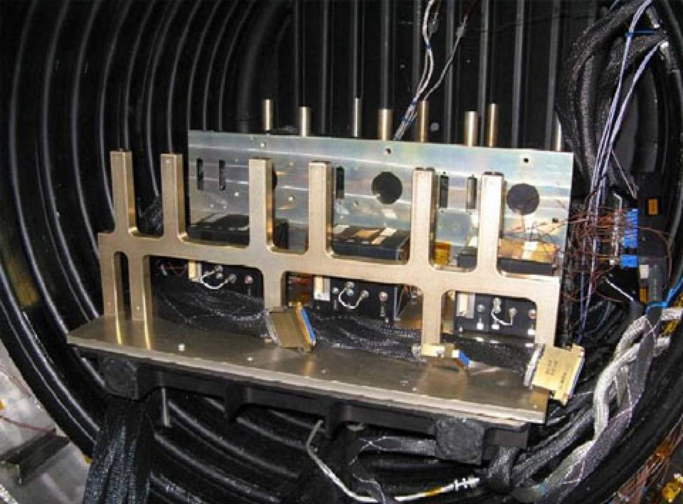
NirSpec CLS EGSE rack under test in IABG
NirSpec Shack-Hartmann
Solar B EIS mounted to the Spacecraft in Japan
SolarB bench testing

Swift UVOT testing at Goddart
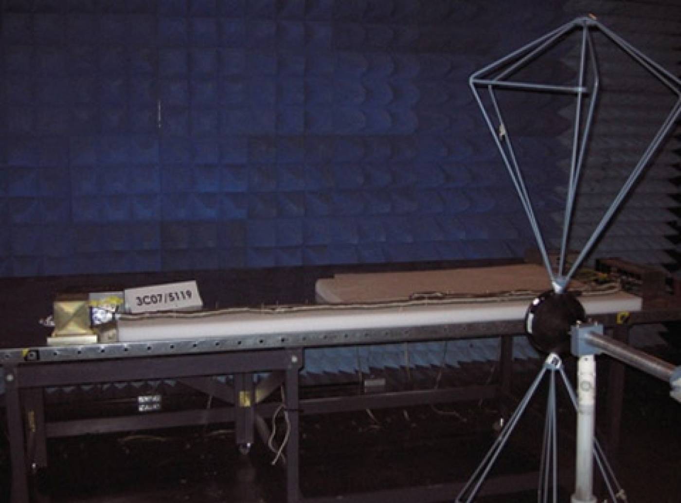
UVIT EMC testing
UVIT high Voltage flight models under integration in Canada