
An earthquake's Richter magnitude was originally defined to be the amplitude of shaking on a Wood-Anderson seismometer of an earthquake 100km away. Since there are very few working Wood-Anderson seismometers around these days, scientists approximate the magnitude using calibration scales based on the distance from the source and the amplitude of seismic waves.
![]()
![]()
![]()
![]() delta comes off a table
delta comes off a table
![]()
and the moment magnitude is given by
![]()
![]()
The energy of an earthquake is proportional to the amplitude squared. In theory, the energy of an earthquake of surface wave magnitude n is equivalent to approximately 100 earthquakes of surface wave magnitude n-1. In reality, the energy is only about 30 times greater and the shaking is only about 10 times greater in intensity. Because of this seismologists can predict the number of smaller earthquakes that are likely to occur after a bigger earthquake using this equation where N is the number of earthquakes of a given magnitude:
![]()
most of the time b is assumed to be equal to 1; for b>1in an area it generaly means that small earthquakes occur frequently; for b<1, it indicates an area that is more prone for a larger earthquake. In volcanic areas where there's lots of earthquake swarms b>1 and b<1 along subduction zones and continental rifts where there's many large earthquakes with few aftershocks.
An earthquake is defined as a sudden slip event along a fault in the subsurface. The first shock reveals a good deal about the nature of the fault. Depending on whether a particular area is compressed or extended by movement along the fault, the first motion p-wave will be upwards (positive) or downwards (negative), respectively. The p-wave first arrivals can be plotted on a stereonet with two planes, drawn along great circles, separating the compressional (positive) p-waves from the extensional (negative) p-waves. These planes are known as nodal planes. Focal mechanisms present a "double-couple" in which either nodal plane is representative of the fault plane. To determine the correct plane, the locations of aftershocks and/or surface geology can be useful.
Let's assume we have a simple strike-slip fault.

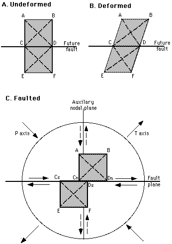
Above is a two-dimensional model for the first-motion radiation pattern of a srike-slip faulting event. A. shows two undeformed blocks before faulting. B. shows the two blocks being deformed as the blocks are sheared to the right. C. sudden loss of cohesion between the two blocks along an E-W striking fault plane; producing an earthquake. The fault squished new material into the upper right and lower left quadrants causing compression. Poisson's ratio states that the volume of material must remain constant, therefore, the material in the two quadrants was uplifted to compensate for the compression. This is expressed as a positive first motion of the p-waves. In the upper left and lower right quadrants material was pulled away by the fault. This is expressed as subsidence of the material and a negative first motion of the p-waves.

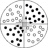
where the dark circles are positive first arrivals and the open circles are negative first arrivals. Next a great circle is drawn that separates the two types of arrivals. The pole to this circle is plotted. The second circle should contain the pole as well as divide the two types of arrivals. The end result is something like this:

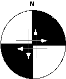
where the dark regions are compressional. This image is the characteristic first motion pattern for strike-slip faults. Here, the nodal planes lie along the E-W and N-S axes. Due to the "double-couple," this fault is either a vertical, E-W striking, right-lateral fault or a vertical, N-S striking, left-lateral fault.
The maximum and minimum compressive stresses can also be determined from first motion diagrams. The minimum compressive stress axis, also know as the T-axis bisects the compressional first arrivals and the maximum compressive stress axis or P-axis bisects the extensional first arrivals.
Normal faults and thrust faults also have characteristic patterns.


The pattern on the left is typical of pure normal faulting and the pattern on the right is typical of pure thrust faulting. By studying the geology one can determine that the left-most nodal plane is the fault plane for both the normal and the thrust faults.
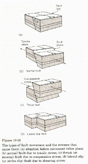
For the normal fault pictured (Fig. 18.16), the P-axis can be represented by a dot at the center of a stereonet (a vertical line) and the T-axis at 45 degrees from the fault plane, bisecting the extensional first arrivals. For the thrust fault, the T-axes can be represented by a dot at the center of a stereonet with the P-axis 45 degrees from the fault plane, bisecting the compressional first arrivals. For the left-lateral strike-slip fault, the P-axis is parallel to the fault and the T-axis is perpendicular to the fault.

It is very unusual to find a pure strike-slip, normal or thrust fault in nature. Most faults consist mainly of one motion with a small component of another. Pure strike-slip faults have first motion diagrams with nodal planes that intersect in the center of the stereonet (as pictured above). Strike-slip faults that have some component of thrust or normal faulting intersect off-center.

This is either a left-lateral or right-lateral strike slip fault with a component of thrust faulting. The nodal planes for pure normal faults and pure thrust faults intersect along the primitive circle (as pictured previously). Strike-slip faults can have components of either normal or thrust faulting, but normal and thrust faults can only have components of strike-slip faulting. Here's the first motion patterns of an oblique normal fault and an oblique thrust fault with a small component of strike slip motion.
 Oblique thrust |
The first motion pattern for thrust faulting with a small component of left lateral strike-slip motion would look the same (except the compression and extension circles would be reversed). |  Oblique normal |
Syllabus |
Problems |
Links |
References |
HTML Guide |
